DIN 6912 – Hex Socket Low Cap Head Screw With Pilot Hole
DIN 6912 specifies the requirements for hexagon socket head cap screws with a low head and a specialized pilot hole. These fasteners are engineered for applications where vertical clearance is limited, but high-precision engagement is required. Unlike standard socket screws, DIN 6912 features a distinct center hole within the hexagonal drive. While it shares a similar low-profile geometry with DIN 7984, the inclusion of the pilot recess allows for specialized tooling and ensures the fastener can be utilized in security or high-vibration environments where drive stability is paramount.
| DIN 6912 - Dimensions | |||||||||||||||||
|---|---|---|---|---|---|---|---|---|---|---|---|---|---|---|---|---|---|
| Thread Size | M4 | M5 | M6 | M8 | M10 | M12 | M14 | M16 | M18 | M20 | M22 | M24 | M27 | M30 | M33 | M36 | |
| dk | Max | 7 | 8.5 | 10 | 13 | 16 | 18 | 21 | 24 | 27 | 30 | 33 | 36 | 40 | 45 | 50 | 54 |
| Min | 6.78 | 8.28 | 9.78 | 12.73 | 15.73 | 17.73 | 20.67 | 23.67 | 26.67 | 29.67 | 32.61 | 65.61 | 39.61 | 44.61 | 49.61 | 53.54 | |
| k | Max | 2.8 | 3.5 | 4 | 5 | 6.5 | 7.5 | 8.5 | 10 | 11 | 12 | 13 | 14 | 16 | 17.5 | 19.5 | 21.5 |
| Min | 2.66 | 3.32 | 3.82 | 4.82 | 6.28 | 7.28 | 8.28 | 9.78 | 10.73 | 11.73 | 12.73 | 13.73 | 15.73 | 17.23 | 19.17 | 21.17 | |
| t1 | Nom | 1.6 | 2 | 2.5 | 3 | 3.5 | 4 | 4.5 | 5.5 | 6 | 6.5 | 7 | 7 | 8.5 | 9 | 10 | 11.5 |
| Max | 1.72 | 2.12 | 2.62 | 3.12 | 3.65 | 4.15 | 4.65 | 5.65 | 6.15 | 6.68 | 7.18 | 7.18 | 8.68 | 9.18 | 10.18 | 11.72 | |
| Min | 1.48 | 1.88 | 2.38 | 2.88 | 3.35 | 3.85 | 4.35 | 5.35 | 5.85 | 6.32 | 6.82 | 6.82 | 8.32 | 8.82 | 9.82 | 11.28 | |
| t2 | Max | 3.6 | 4.3 | 5.3 | 6.86 | 7.86 | 9.36 | 10.36 | 11.93 | 12.93 | 14.43 | 15.43 | 16.43 | 17.43 | 19.52 | 20.52 | 24.52 |
| Min | 3.3 | 4 | 5 | 6.5 | 7.5 | 9 | 10 | 11.5 | 12.5 | 14 | 15 | 16 | 17 | 19 | 20 | 24 | |
| dh | Max | 2.06 | 2.56 | 3.06 | 4.075 | 5.075 | 6.075 | 7.09 | 8.09 | 8.09 | 10.09 | 10.09 | 12.11 | 12.11 | 15.11 | 16.61 | 18.11 |
| Min | 2 | 2.5 | 3 | 4 | 5 | 6 | 7 | 8 | 8 | 10 | 10 | 12 | 12 | 15 | 16.5 | 18 | |
| s | Nom | 3 | 4 | 5 | 6 | 8 | 10 | 12 | 14 | 14 | 17 | 17 | 19 | 19 | 22 | 24 | 27 |
| Max | 3.1 | 4.12 | 5.14 | 6.14 | 8.175 | 10.175 | 12.212 | 14.212 | 14.212 | 17.23 | 17.23 | 19.275 | 19.275 | 22.275 | 24.275 | 27.275 | |
| Min | 3.02 | 4.02 | 5.02 | 6.02 | 8.025 | 10.025 | 12.032 | 14.032 | 14.032 | 17.05 | 17.05 | 19.065 | 19.065 | 22.065 | 24.065 | 27.065 | |
| e | Min | 3.44 | 4.58 | 5.72 | 6.86 | 9.15 | 11.43 | 13.72 | 16 | 16 | 19.44 | 19.44 | 21.73 | 21.73 | 25.15 | 27.43 | 30.85 |
| v | Max | 0.4 | 0.5 | 0.6 | 0.8 | 1 | 1.2 | 1.4 | 1.6 | 1.8 | 2 | 2.2 | 2.4 | 2.7 | 3 | 3.3 | 3.6 |
| r | Min | 0.2 | 0.2 | 0.25 | 0.4 | 0.4 | 0.6 | 0.6 | 0.6 | 0.6 | 0.8 | 0.8 | 0.8 | 1 | 1 | 1 | 1 |
| lf | Max | 0.6 | 0.6 | 0.68 | 1.02 | 1.02 | 1.45 | 1.45 | 1.45 | 1.87 | 2.04 | 2.04 | 2.04 | 2.89 | 2.89 | 2.89 | 2.89 |
| dw | Min | 6.2 | 7.7 | 9.2 | 12.03 | 15.03 | 17.03 | 19.83 | 22.83 | 25.83 | 28.83 | 31.61 | 34.61 | 38.61 | 43.61 | 48.61 | 52.34 |
| da | Max | 4.7 | 5.7 | 6.8 | 9.2 | 11.2 | 13.7 | 15.7 | 17.7 | 20.2 | 22.4 | 24.4 | 26.4 | 30.4 | 33.4 | 36.4 | 39.4 |
| ds | Max | 4 | 5 | 6 | 8 | 10 | 12 | 14 | 16 | 18 | 20 | 22 | 24 | 27 | 30 | 33 | 36 |
| Min | 3.82 | 4.82 | 5.82 | 7.78 | 9.78 | 11.73 | 13.73 | 15.73 | 17.73 | 19.67 | 21.67 | 23.67 | 26.67 | 29.67 | 32.61 | 65.61 | |
| b (Ref) | l ≤ 125 | 14 | 16 | 18 | 22 | 26 | 30 | 34 | 38 | 42 | 46 | 50 | 54 | 60 | 66 | 72 | 78 |
| l ≤ 200 | — | — | — | — | 32 | 36 | 40 | 44 | 48 | 52 | 56 | 60 | 66 | 72 | 78 | 84 | |
| l > 200 | — | — | — | — | — | — | — | 57 | 61 | 65 | 69 | 73 | 79 | 85 | 91 | 97 | |
Note: All measurement are in mm
Disclaimer: The dimensions presented on this page are based on the applicable industry standard. However, actual product measurements may vary slightly due to manufacturing practices, material selection, surface finish, and specified tolerance classes. Buyers and sourcing professionals are encouraged to verify final specifications with the manufacturer or supplier prior to procurement, particularly for critical applications.
Legend
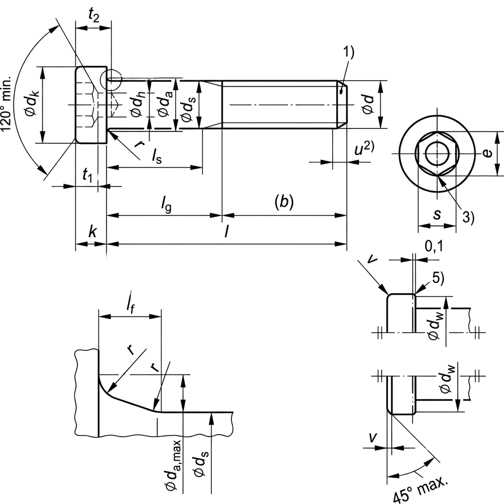
- dk – Head diameter.
- da – Transition diameter (max).
- ds – Shank diameter.
- k – Head height.
- s – Width across flats of the internal hexagon socket. determining the required allen keys
- t1 – Total depth of the internal hexagon socket.
- t2 – Depth of the pilot hole (nominal/min/max).
- e – Width across corners of the internal hexagon socket (min).
- dw – Minimum bearing diameter under the head.
- b – Reference thread length (dependent on screw length ).
- r – Radius of the underhead fillet (min).
- dh – Diameter of the pilot hole.
- v – Maximum underhead fillet depth/curvature.
- lf – Thread run-out (max).
- Ref (Reference value) – A theoretical dimension provided for information and design guidance only. Reference values (like b) are not requirements for inspection but assist in geometry calculation.
Technical Note
- lg max – The maximum length of the unthreaded portion, calculated as nominal length (l) - reference thread length (b).
-
The minimum value of ls (unthreaded shank length) can be determined by:
ls min = lg max − 5P
where P is the thread pitch. - Pilot Hole – Unlike low-cap head screws under DIN 7984, DIN 6912 screws feature a pilot hole (dh) within the socket, which is reflected in the (t1) and (t2) dimensions.
-
Standard nominal lengths (l) under DIN 6912 are generally available in the following ranges:
- For sizes M4 – M16: 10 mm to 140 mm
- For sizes M18 – M36: 20 mm to 200 mm