ISO 4762 – Hexagon Socket Cap Head Screw Dimensions
ISO 4762 is the primary international standard for hexagon socket head cap screws (SHCS). These high-strength fasteners are designed with a cylindrical head and an internal hexagonal drive, enabling high-torque tightening in recessed or confined areas where traditional hex bolts cannot be used.
ISO 4762 is the modern global equivalent to the German DIN 912 standard. For the vast majority of engineering applications, these two standards are considered functionally interchangeable, sharing identical dimensions for head diameter (dk), head height (k), and socket size (s).
| ISO 4762 - Dimensions | |||||||||||||||||||||
|---|---|---|---|---|---|---|---|---|---|---|---|---|---|---|---|---|---|---|---|---|---|
| Thread Size | M1.6 | M2 | M2.5 | M3 | M4 | M5 | M6 | M8 | M10 | M12 | M14 | M16 | M20 | M24 | M30 | M36 | M42 | M48 | M56 | M64 | |
| dk | Max | 3.14 | 3.98 | 4.68 | 5.68 | 7.22 | 8.72 | 10.22 | 13.27 | 16.27 | 18.27 | 21.33 | 24.33 | 30.33 | 36.39 | 45.39 | 54.46 | 63.46 | 72.46 | 84.54 | 96.54 |
| Min | 2.86 | 3.62 | 4.32 | 5.32 | 6.78 | 8.28 | 9.78 | 12.73 | 15.73 | 17.73 | 20.67 | 23.67 | 29.67 | 35.61 | 44.61 | 53.54 | 62.54 | 71.54 | 83.46 | 95.46 | |
| k | Max | 1.6 | 2 | 2.5 | 3 | 4 | 5 | 6 | 8 | 10 | 12 | 14 | 16 | 20 | 24 | 30 | 36 | 42 | 48 | 56 | 64 |
| Min | 1.46 | 1.86 | 2.36 | 2.86 | 3.82 | 4.82 | 5.7 | 7.64 | 9.64 | 11.57 | 13.57 | 15.57 | 19.48 | 23.48 | 29.48 | 35.38 | 41.38 | 47.38 | 55.26 | 63.26 | |
| s | Nom | 1.5 | 1.5 | 2 | 2.5 | 3 | 4 | 5 | 6 | 8 | 10 | 12 | 14 | 17 | 19 | 22 | 27 | 32 | 36 | 41 | 46 |
| Max | 1.58 | 1.58 | 2.08 | 2.58 | 3.08 | 4.095 | 5.14 | 6.14 | 8.175 | 10.175 | 12.212 | 14.212 | 17.23 | 19.275 | 22.275 | 27.275 | 32.33 | 36.33 | 41.33 | 46.33 | |
| Min | 1.52 | 1.52 | 2.02 | 2.52 | 3.02 | 4.02 | 5.02 | 6.02 | 8.025 | 10.025 | 12.032 | 14.032 | 17.05 | 19.065 | 22.065 | 27.065 | 32.08 | 36.08 | 41.08 | 46.08 | |
| e | Min | 1.733 | 1.733 | 2.303 | 2.873 | 3.443 | 4.583 | 5.723 | 6.863 | 9.149 | 11.429 | 13.716 | 15.996 | 19.437 | 21.734 | 25.154 | 30.854 | 36.571 | 41.131 | 46.831 | 52.531 |
| t | Min | 0.7 | 1 | 1.1 | 1.3 | 2 | 2.5 | 3 | 4 | 5 | 6 | 7 | 8 | 10 | 12 | 15.5 | 19 | 24 | 28 | 34 | 38 |
| w | Min | 0.55 | 0.55 | 0.85 | 1.15 | 1.4 | 1.9 | 2.3 | 3.3 | 4 | 4.8 | 5.8 | 6.8 | 8.6 | 10.4 | 13.1 | 15.3 | 16.3 | 17.5 | 19 | 22 |
| r | Min | 0.1 | 0.1 | 0.1 | 0.1 | 0.2 | 0.2 | 0.25 | 0.4 | 0.4 | 0.6 | 0.6 | 0.6 | 0.8 | 0.8 | 1 | 1 | 1.2 | 1.6 | 2 | 2 |
| da | Max | 2 | 2.6 | 3.1 | 3.6 | 4.7 | 5.7 | 6.8 | 9.2 | 11.2 | 13.7 | 15.7 | 17.7 | 22.4 | 26.4 | 33.4 | 39.4 | 45.6 | 52.6 | 63 | 71 |
| ds | Max | 1.6 | 2 | 2.5 | 3 | 4 | 5 | 6 | 8 | 10 | 12 | 14 | 16 | 20 | 24 | 30 | 36 | 42 | 48 | 56 | 64 |
| Min | 1.46 | 1.86 | 2.36 | 2.86 | 3.82 | 4.82 | 5.82 | 7.78 | 9.78 | 11.73 | 13.73 | 15.73 | 19.67 | 23.67 | 29.67 | 35.61 | 41.61 | 47.61 | 55.54 | 63.54 | |
| dw | Min | 2.72 | 3.48 | 4.18 | 5.07 | 6.53 | 8.03 | 9.38 | 12.33 | 15.33 | 17.23 | 20.17 | 23.17 | 28.87 | 34.81 | 43.61 | 52.54 | 61.34 | 70.34 | 82.26 | 94.26 |
| b | Ref | 15 | 16 | 17 | 18 | 20 | 22 | 24 | 28 | 32 | 36 | 40 | 44 | 52 | 60 | 72 | 84 | 96 | 108 | 124 | 140 |
Note: All measurement are in mm
Disclaimer: The dimensions presented on this page are based on the applicable industry standard. However, actual product measurements may vary slightly due to manufacturing practices, material selection, surface finish, and specified tolerance classes. Buyers and sourcing professionals are encouraged to verify final specifications with the manufacturer or supplier prior to procurement, particularly for critical applications.
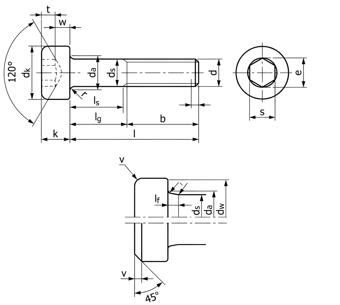
Legend
- dk – Head diameter.
- da – Transition diameter (max).
- ds – Shank diameter.
- k – Head height.
- s – Width across flats of the internal hexagon socket.
- t – Minimum depth of the internal hexagon socket.
- e – Width across corners of the internal hexagon socket (min).
- dw – Minimum bearing diameter under the head.
- b – Reference thread length.
- r – Radius of the underhead fillet (min).
- w – Minimum wall thickness between the socket and outer head diameter.
- Ref (Reference value) – A theoretical dimension provided for information and design guidance only. Reference values (like b) are not requirements for inspection but assist in geometry calculation.
Technical Note
-
The maximum value of lg can be determined by:
lg max = nominal length − b
where b is the reference thread length. -
The minimum value of ls can be determined by:
ls min = lg max − 5P
where P is the thread pitch. -
Standard nominal lengths (l) according to ISO 4762 are generally available in the following ranges:
- For sizes M1.6 – M8: 2.5 mm to 80 mm
- For sizes M10 – M36: 16 mm to 200 mm
- For sizes M42 – M64: 50 mm to 300 mm