ISO 7380-1 & 7380-2 | Hex Socket Button Head Screw Dimensions
ISO 7380 specifies the technical requirements for hexagon socket button head screws with thread sizes ranging from M3 to M16. These fasteners are characterized by their rounded, low-profile head design, making them an ideal choice for applications where a clean, aesthetic finish is required without sacrificing structural integrity.
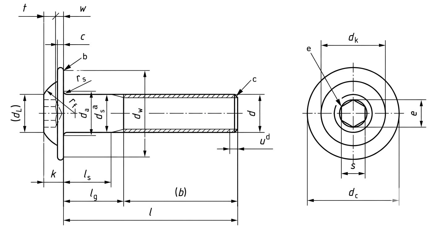
The standard is divided into two distinct parts: ISO 7380-1 (standard button head) and ISO 7380-2 (button head with an integrated flange or collar). Due to their streamlined shape, these screws are widely utilized in the automotive, aerospace, and consumer electronics sectors, particularly where space is limited or a protruding fastener head could pose a safety risk.
| ISO 7380-1 - Dimensions | |||||||||
|---|---|---|---|---|---|---|---|---|---|
| Thread Size | M3 | M4 | M5 | M6 | M8 | M10 | M12 | M16 | |
| dk | Min | 5.4 | 7.24 | 9.14 | 10.07 | 13.57 | 17.07 | 20.48 | 27.48 |
| Max | 5.7 | 7.6 | 9.5 | 10.5 | 14 | 17.5 | 21 | 28 | |
| dl | Ref | 2.6 | 3.8 | 5 | 6 | 7.7 | 10 | 12 | 16 |
| rf | Min | 3.3 | 4.2 | 5.25 | 5.65 | 7.45 | 9.2 | 10.5 | 14.5 |
| Max | 3.7 | 4.6 | 5.75 | 6.15 | 7.95 | 9.8 | 11.2 | 15.3 | |
| k | Min | 1.4 | 1.95 | 2.5 | 3 | 4.1 | 5.2 | 6.24 | 8.44 |
| Max | 1.65 | 2.2 | 2.75 | 3.3 | 4.4 | 5.5 | 6.6 | 8.8 | |
| s | Nom | 2 | 2.5 | 3 | 4 | 5 | 6 | 8 | 10 |
| Min | 2.02 | 2.52 | 3.02 | 4.02 | 5.02 | 6.02 | 8.025 | 10.025 | |
| Max | 2.08 | 2.58 | 3.08 | 4.095 | 5.14 | 6.14 | 8.175 | 10.175 | |
| e | Min | 2.303 | 2.873 | 3.443 | 4.583 | 5.723 | 6.863 | 9.149 | 11.429 |
| t | Min | 1.04 | 1.3 | 1.56 | 2.08 | 2.6 | 3.12 | 4.16 | 5.2 |
| w | Min | 0.2 | 0.3 | 0.38 | 0.74 | 1.05 | 1.45 | 1.63 | 2.25 |
| rs | Min | 0.1 | 0.2 | 0.2 | 0.25 | 0.4 | 0.4 | 0.6 | 0.6 |
| rt | Min | 0.3 | 0.4 | 0.45 | 0.5 | 0.7 | 0.7 | 1.1 | 1.1 |
| da | Max | 3.6 | 4.7 | 5.7 | 6.8 | 9.2 | 11.2 | 13.7 | 17.7 |
| ds | Min | 2.86 | 3.82 | 4.82 | 5.82 | 7.78 | 9.78 | 11.73 | 15.73 |
| Max | 3 | 4 | 5 | 6 | 8 | 10 | 12 | 16 | |
| dw | Min | 5 | 6.84 | 8.74 | 9.57 | 13.07 | 16.57 | 19.68 | 26.68 |
| b | Ref | 18 | 20 | 22 | 24 | 28 | 32 | 36 | 44 |
Note: All measurement are in mm
Disclaimer: The dimensions presented on this page are based on the applicable industry standard. However, actual product measurements may vary slightly due to manufacturing practices, material selection, surface finish, and specified tolerance classes. Buyers and sourcing professionals are encouraged to verify final specifications with the manufacturer or supplier prior to procurement, particularly for critical applications.
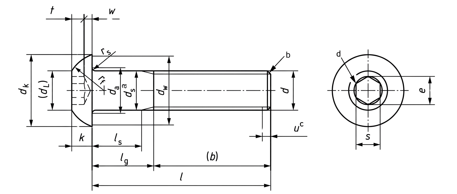
Legend
- da – Maximum diameter of the head at the top edge (outside crown diameter).
- dw – Minimum bearing diameter under the head (contact surface diameter).
- dl – Reference diameter of the head profile transition.
- ds – Unthread part or the screw shank diameter.
- dk – Head diameter measured at its widest cylindrical portion.
- k – Head height measured from the bearing surface to the top of the button head.
- rf – Radius of the button head dome.
- rs – Underhead radius for a screw with unthreaded shank.
- rt – Underhead radius for a fully threaded screws.
- b – Thread length (reference value), measured from the end of the screw to the start of the unthreaded portion (if applicable).
- e – Minimum width across corners of the internal hex socket.
- t – Minimum depth of the internal hex socket.
- w – Minimum wall thickness between the socket and outer head diameter.
- s – Width across flats of the internal hex socket (nominal hex key or allen key size).
Technical Note
-
The maximum value of lg
can be determined by:
lg max = nominal length − b
where b is the reference thread length. -
The minimum value of ls
can be determined by:
ls min = lg max − 5P
where P is the thread pitch. - Ref (Reference value) – A theoretical dimension provided for information and design guidance only. Reference values (like m or rf) are not used as requirements for inspection but help in visualizing or calculating geometry.